
How to Size an Air Compressor for a Multi Bay Workshop
WORKSHOP ENGINEERING / TECHNICAL GUIDE 05
How to Size an Air Compressor for a Multi Bay Workshop
A practical guide to estimating CFM demand, checking free air delivery, understanding pressure drop and planning compressed-air distribution across multiple service bays.
Choosing an air compressor by horsepower alone does not prevent these problems. The starting point is to estimate the usable air volume required during realistic working conditions, then check whether the compressor and distribution network can deliver that air at the pressure required by the connected equipment.
For a multi bay workshop, the calculation should consider tool consumption, simultaneous demand, intermittent and continuous use, receiver capacity, pipework restrictions, air treatment, leakage, electrical supply and planned expansion. Each factor influences the final equipment and installation decision.
The system-sizing sequence
Record each tool’s documented air consumption, pressure and operating pattern.
Identify the tools that can realistically operate together during busy periods.
Use free air delivery (FAD) at the relevant pressure, not horsepower or displacement alone.
Review receiver recovery, air treatment, pipework pressure drop and installation requirements.
01 / DEMAND INVENTORY
Start with an air demand inventory for every bay
Before comparing compressor models, document the pneumatic tools and machines used throughout the workshop. Manufacturer-rated air consumption and required operating pressure should be the primary reference points.
Record whether each tool operates continuously or intermittently, how long it typically runs, and whether its use overlaps with equipment in other bays. If a specification is missing, request it from the equipment supplier instead of assuming a precise consumption figure.
| Tool or process | Record | Sizing consideration |
|---|---|---|
| Impact wrench | Air consumption, pressure and trigger time | Intermittent demand may overlap across bays. |
| Spray gun | Air consumption during spraying and required pressure | Pressure variation can affect atomisation and finish. |
| Tyre service equipment | Machine-specific requirements and operating cycle | Several machines may demand air simultaneously. |
| Blow gun or cleaning tool | Duration and frequency of use | Uncontrolled use can add significant demand. |
| Specialist machinery | Exact manufacturer specification | Some processes have minimum pressure or air-quality requirements. |
Use the inventory to create at least two operating scenarios: a normal working period and a credible busy period. Include additional scenarios for processes that run continuously, such as painting, where applicable.
02 / UNDERSTANDING CAPACITY
Free air delivery versus compressor displacement
Compressor displacement describes the theoretical volume swept by the compressor mechanism under its stated conditions. Free air delivery (FAD) is generally more useful for sizing because it represents the air delivered under a specified test condition.
When comparing models, confirm the stated FAD, measurement conditions and intended working pressure. Figures from different test conditions should not be treated as directly equivalent.
DISPLACEMENT
Theoretical volume
Describes the volume swept by the compressor mechanism. It should not be assumed to equal usable delivered air.
FREE AIR DELIVERY
Delivered air
Provides a more relevant basis for comparing compressor supply with the calculated demand.
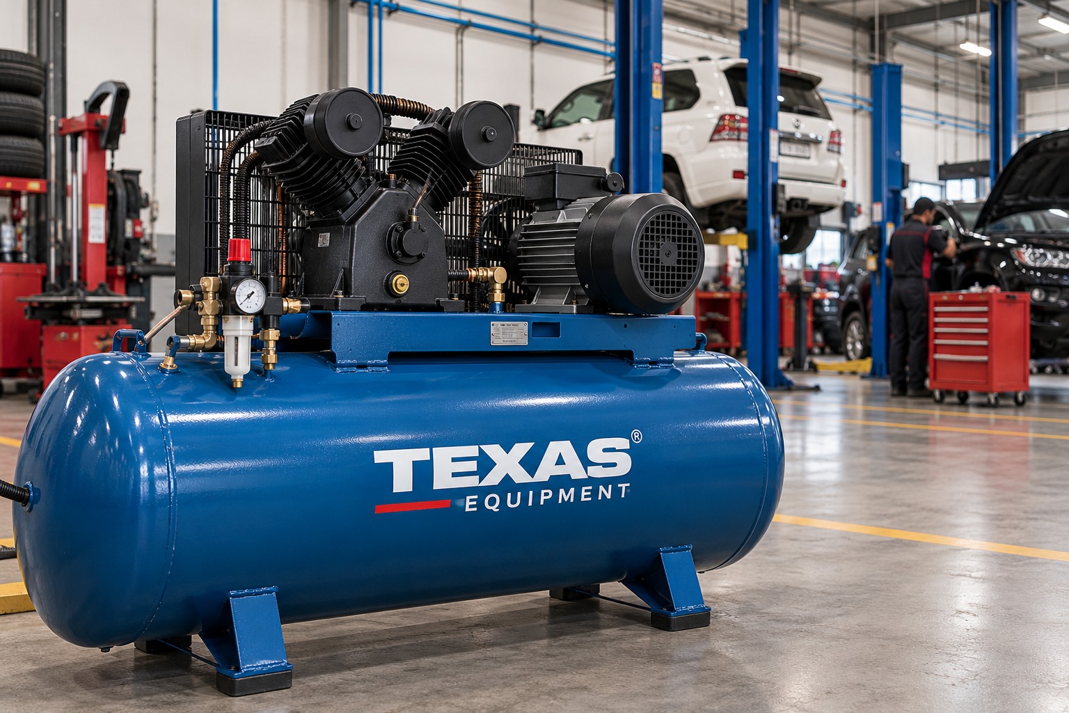
For example, Texas Equipment lists a 5 HP industrial compressor with published FAD of 389.99 L/min and a 7.5 HP model with FAD of 536.67 L/min. The published specifications also include displacement figures, which are different from FAD. Verify the current product datasheet and the relevant delivery conditions before using these values in a project calculation.
View 5 HP compressor specifications | View 7.5 HP compressor specifications
03 / CFM CALCULATION
How to calculate simultaneous CFM demand
For each realistic operating scenario, add the documented air consumption of the tools expected to run together. Use consistent units and ratings that apply to the required operating conditions.
BASIC DEMAND FORMULA
Simultaneous air demand = Sum of air consumption for tools expected to operate together
Compare the resulting demand estimate with the compressor’s documented FAD at the relevant working pressure.
Worked example: three tools in a busy period
The figures below are illustrative only. They are not specifications for particular Texas Equipment products or a recommendation for a particular compressor.
| Tool | Illustrative air demand | Operating pattern |
|---|---|---|
| Tool A | 4 CFM | Intermittent |
| Tool B | 5 CFM | Intermittent |
| Tool C | 7 CFM | Used during selected jobs |
| All three together | 16 CFM | Peak scenario |
In this illustrative scenario, tools A and B create a combined demand of 9 CFM when used together. If tool C also operates, the estimated simultaneous demand rises to 16 CFM.
The next step is not to select a compressor based on this number alone. Compare each scenario with documented FAD at the required pressure, then review operating duration, compressor recovery, air-treatment restrictions, distribution losses and the consequences of future demand.
Do not apply an arbitrary safety factor. Any allowance for leakage, future equipment or uncertainty should have a documented basis. If the calculated demand is close to available supply, ask a competent supplier or installer to review the assumptions.
04 / PRESSURE AT THE POINT OF USE
Why compressor pressure is not the same as tool pressure
A compressor may operate within a pressure band, but the tool receives air through a network of filters, dryers, regulators, hoses, couplings and distribution pipes. Each component can introduce a pressure loss.
A static pressure reading taken when no tools are operating does not prove that the system can maintain the required pressure under load. The important measurement is pressure at the relevant point of use while air is flowing, following the tool manufacturer’s instructions.
Pressure drops across several bays
Review total demand, compressor delivery, receiver recovery, common filters and the main distribution line.
Only one bay has low pressure
Inspect that branch, including local hoses, quick couplings, regulators, filters and possible restrictions.
Spray quality changes during operation
Check pressure under flow at the gun and investigate air-treatment requirements alongside the coating setup.
Pressure falls during repeated peak demand
Assess sustained compressor delivery, receiver recovery and the timing of concurrent tool use.
05 / PIPEWORK DESIGN
Account for compressed-air pipe sizing and distribution losses
A compressor may appear adequate on paper while a distant service bay receives insufficient pressure. The distribution network can become the limiting factor when pipework is too restrictive for the required flow.
Pressure drop is affected by the pipe’s internal diameter, total run length, bends, tees, filters, regulators, couplings and the volume of air flowing through the network. Long runs, narrow branches and undersized fittings can become especially noticeable when several tools operate together.
What the installer should evaluate
- The layout of the main line and all branches serving the bays.
- The longest route from the receiver or main distribution point to the tool.
- Expected flow rates and acceptable pressure drop at peak demand.
- Restrictions introduced by filters, regulators, hoses and quick couplings.
- Future branch connections and the actual planned expansion of the workshop.
- Access for inspection, drainage, maintenance and safe installation.
Ask the installer to document the design flow, expected pressure drop and basis for pipe sizing in the quotation. For a multi bay workshop in the UAE, also consider the planned pipe route, ventilation around the compressor, electrical supply, dust conditions and space for future equipment.
06 / RECEIVER CAPACITY
What does the receiver tank actually do?
The receiver stores compressed air and can help manage short peaks in demand. When correctly selected for the application, it can also help manage compressor cycling and provide a buffer while the compressor recovers.
However, the receiver does not create additional sustained compressor capacity. If connected tools consume air faster than the compressor can deliver it over the operating cycle, a larger tank may delay the pressure drop but will not resolve the underlying mismatch.
Receiver can help with
- Short demand peaks
- Temporary stored-air supply
- Managing cycling when correctly sized
Receiver cannot replace
- Insufficient sustained FAD
- Undersized distribution lines
- Leak repairs or blocked filters
Receiver selection and installation must follow the compressor manufacturer’s guidance and applicable pressure-vessel requirements. Protective devices, inspections and drainage arrangements must be suitable for the installation. Never modify a receiver or bypass its safety equipment to resolve a pressure problem.
07 / AIR QUALITY
Include filters, dryers and drainage in the system design
Moisture, particles and oil carryover can affect pneumatic equipment and finishing processes. The required air treatment depends on the application and the specifications of the connected equipment.
A general workshop tool and an automotive paint process may have different air-quality requirements. Select filters, separators and dryers according to the process requirements rather than assuming that one general-purpose filter is suitable for every bay.
Include condensate drainage and routine maintenance in the plan. Restricted filters, neglected drains and contaminated lines can reduce performance even when the compressor’s nominal capacity appears sufficient.
For a system that includes painting, verify the coating process requirements and the air-quality recommendations for the specific equipment. A pressure regulator alone does not remove moisture or all contaminants.
08 / TROUBLESHOOT BEFORE UPGRADING
Check for leaks and restrictions before buying a larger compressor
Pressure problems do not always mean that the compressor is undersized. Air leaks, damaged hoses, poor couplings, blocked filters and unnecessary blow-gun use can increase demand or restrict delivery.
Before investing in a larger unit, review the existing system for audible leaks, damaged components, neglected filters and avoidable air consumption. If the workshop already has an operating system, record pressure at the receiver and representative tools, compressor run time and the periods when pressure drops occur.
These observations help distinguish among insufficient compressor delivery, excessive simultaneous demand, leakage, poor distribution and local restrictions. Repairing the actual problem may be more effective than replacing equipment without a diagnosis.
09 / BUYING SPECIFICATION
What to include in an air compressor quotation request
Once the demand scenarios are documented, the supplier can assess suitable compressor options and the supporting equipment. A useful quotation should explain the assumptions behind the recommendation rather than providing only horsepower and tank capacity.
Workshop compressor specification checklist
- □ Tool inventory with documented air consumption
- □ Normal and peak simultaneous demand scenarios
- □ Required operating pressure and FAD at that pressure
- □ Receiver capacity and compressor duty requirements
- □ Pipework layout and expected distribution pressure drop
- □ Air treatment, filters, dryers and drainage requirements
- □ Electrical supply, starting requirements and installation space
- □ Maintenance access, service requirements and operating limits
- □ Planned future tools, additional bays and any stated uncertainty
If the supplier’s recommendation depends on an assumption about simultaneous tool use, ask for that assumption to be stated. Where consumption data is missing or demand is uncertain, use a measured estimate or request a proper assessment rather than presenting an invented figure as manufacturer data.
10 / INSTALLATION AND COMMISSIONING
Verify performance after the system is installed
A sizing calculation is only the first stage. After installation, the compressor, receiver, air treatment and distribution network should be checked under realistic operating conditions by qualified personnel.
- Confirm the installation: verify that the compressor and supporting equipment match the approved specification.
- Check the air system: inspect the filters, drains, regulators, connections and safety devices.
- Test representative bays: check pressure at selected tools under realistic demand, not only at the receiver while idle.
- Record baseline readings: document operating pressure, demand conditions and any observed recovery issues.
- Resolve discrepancies: investigate restrictions, leaks, inadequate delivery or incorrect assumptions before changing settings or replacing equipment.
Confirm the available electrical supply, phase, starting requirements, ventilation, service clearances and installation constraints before selecting a compressor. A model that meets the estimated air demand may still be unsuitable if the proposed site cannot meet its installation requirements.
11 / EXPANSION PLANNING
Plan for additional bays without oversizing blindly
If the workshop expects to add another bay, machine or shift, include the expected equipment in the demand worksheet before choosing a compressor. Use actual specifications wherever possible.
An undefined allowance for future growth can increase capital cost, electrical requirements and maintenance without solving the right problem. A documented expansion plan helps the supplier assess whether the compressor, receiver, distribution network and air treatment system can support the intended operating model.
Revisit the demand calculation when the workshop adds equipment or changes its service mix. A system that suited the original workflow may no longer meet demand after usage patterns change.
FREQUENTLY ASKED QUESTIONS
Air Compressor Sizing FAQs
1. Can I size an air compressor by horsepower alone?
No. Horsepower is only one specification. Estimate the simultaneous demand of connected tools and compare it with the compressor’s documented free air delivery at the required operating pressure.
2. Does a larger receiver fix an undersized compressor?
No. A receiver can supply stored air during short peaks, but it cannot provide sustained air indefinitely when demand exceeds compressor delivery. The underlying supply-demand mismatch must be assessed.
3. Should I add every tool’s air consumption together?
Calculate realistic simultaneous-use scenarios using manufacturer specifications. Do not assume that every tool operates continuously, but do not assume that only one tool will ever run at a time in a multi bay workshop.
4. Why does a distant bay have lower air pressure?
Possible causes include restrictive pipework, long runs, undersized hoses, couplings, filters or regulators, and high simultaneous demand. Check pressure at the tool under flow and inspect the local branch before assuming the compressor itself is undersized.
5. What should a compressor sizing quotation include?
Request the demand assumptions, documented FAD at the target pressure, receiver details, duty requirements, air treatment recommendations, pipework design basis, electrical requirements, installation conditions and maintenance needs.
Explore Air Compressor Options
Once the demand calculation and installation requirements are clear, compare the available compressor categories and product specifications. Select equipment based on documented delivery, required pressure, operating pattern and system compatibility.
TEXAS EQUIPMENT UAE
Size the Complete Air System, Not Just the Compressor
Prepare your tool inventory, required operating pressures, simultaneous-demand scenarios and workshop layout before requesting a recommendation. This gives the supplier a clearer basis for assessing compressor capacity, receiver requirements and distribution losses.
Sharjah showroom
Shop #15 BMW Road, Industrial Area 2, Sharjah, UAE
Phone: +971 6 552 9860
WhatsApp: +971 54 320 1243
Abu Dhabi branch: M9, 6th Street, Musaffah Industrial Area, Abu Dhabi
WhatsApp: +971 50 409 4965
Compressor specifications and availability may change. Verify current manufacturer data and operating conditions before purchase. Pressure systems must be selected, installed and maintained by qualified personnel in accordance with applicable requirements.